
SR-71 BLACKBIRD LAB · Educational · AN ILLUSTRATIVE MODEL
Where should the shock wave be?
You watched one SR-71 video. You’re now in charge of the inlet.
At three times the speed of sound the Blackbird’s engines could not breathe the air as it arrived. Two inlets slowed it with shock waves, and where those shocks stood decided whether the airplane cruised or lost a whole engine’s thrust in an instant. This lab lets you move the shocks yourself, in a schematic inlet built from NASA’s published relationships.
- 01A short narrated explorationNine captioned steps that point at the parts and change the controls for you. Text only, no audio. Skip out at any time.
- 02The hands-on experimentSet the Mach number, take the spike or the bypass doors off automatic, and read the state: started, marginal or unstarted.
- 03The technical dossierWhat an unstart is and is not, what the spike and the doors do, the materials and the propulsion chapters, every claim with its page.
01 / THE EXPERIMENT · ILLUSTRATIVE MODEL, NOT THE SR-71’S INLET
An inlet you can unstart.
A cross-section of an axisymmetric mixed-compression inlet: a translating spike, a cowl whose inside narrows to a throat and widens again into a subsonic diffuser, forward bypass doors and an engine face. The relationships are NASA’s; the proportions, schedules and thresholds are this model’s, and the panel below the drawing says exactly which is which.
Step 1 of 9 · NARRATED EXPLORATION
Air arriving too fast
Illustrative, not the SR-71’s inlet: the drawn proportions, the spike travel, the automatic schedules, the engine-demand line, the bypass capacity and the marginal threshold are this model’s. What is NASA’s: the oblique-shock angle for the stated wedge, the isentropic area relation for the throat Mach number, the normal-shock loss, and the roles of the spike and the doors (see “What this model represents”).
COMPUTED STATE
Started
- Spillage: the spike shock crosses the lip radius ahead of the cowl, so part of the compressed air passes outside.
- Impingement: the spike shock enters the cowl and strikes its inside (heating and reflected shocks are not modelled).
- Supercritical: the terminal shock stands far down the diffuser where the duct Mach number is higher; more loss, no unstart risk.
- Choked throat: the throat cannot pass the flow behind the spike shock, so the shock cannot be swallowed.
- Detached: below the wedge’s attachment Mach number the model has no oblique shock at all.
1.2 to 3.4 in steps of 0.1. Mach 3.2 is the Blackbird’s design cruise (NASA FS-030, p. 2); every other number here is just a setting of the model.
0 % is full forward, 100 % full aft. Automatic follows the model’s schedule: the position that holds the throat Mach number near 1.3 (the real spike was scheduled with flight conditions to set the throat Mach number: NASA TM-4207, p. 3). No travel in inches is claimed.
Automatic bleeds just enough to hold the terminal shock a little behind the throat, the model’s stand-in for the real closed loop on duct pressure (NASA TM-4207, p. 3).
Model readout: the numbers behind the state
All values are properties of this schematic inlet and its stated assumptions. “Model total-pressure recovery” is the product of the oblique and terminal shock losses from NASA Glenn’s shock relations for this shock train; it is not an SR-71 figure. “Unstart margin” is the fraction of the throat-to-lip distance still ahead of the terminal shock, an illustrative number.
WHAT THIS MODEL REPRESENTS
- The oblique shock from the spike, from the theta-beta-Mach relation for a two-dimensional wedge of 10°, the model’s stand-in for the cone (NASA Glenn, Oblique Shock Waves). A cone of the same half-angle gives a somewhat smaller shock angle; that is not computed.
- Internal compression: supersonic flow treated as isentropic from the capture station to the throat, so the throat Mach number follows from the drawn area ratio (NASA Glenn, Isentropic Flow Equations, eq. 9). A throat too small for the flow means the shock cannot be swallowed.
- A terminal normal shock that stands where captured flow balances what the engine and the doors accept: an excess pushes it toward the lip, a deficit pulls it into the diffuser. The engine-demand line, the door capacity, the spillage rule, the “marginal” band at 55 % of the way to the lip and the automatic schedules are illustrative constants.
- Loss across each shock from the normal-shock total-pressure relation (NASA Glenn, Normal Shock Wave Equations), the reason the terminal shock belongs near the throat.
- The roles of the parts, as NASA describes them: the spike scheduled to set the throat Mach number, the doors positioning the terminal shock (TM-4207, p. 3); the unstart as the terminal shock moving from the throat to the cowl lip (TM-4207, p. 5).
WHAT IT DOES NOT REPRESENT
- The SR-71’s actual inlet schedule, spike travel in inches, door positions, starting or unstart Mach numbers, or any limitation. None of those come from the sources on this page, so none appear.
- Performance curves, thrust, temperature distributions or a validated digital twin. The recovery number belongs to this drawing.
- Time and memory: the model is quasi-static, with no hysteresis and no restart sequence. A real inlet that unstarts does not simply restart when the controls are put back.
- The J58 engine cycle. NASA’s fact sheet says the air that bypassed the engines to the afterburners and ejector nozzles acted as a ramjet; this page does not say the J58 turned into one.
- Anything classified or nonpublic. Every relationship and fact is from the public NASA documents listed in the source drawer.
02 / THE TECHNICAL DOSSIER · UNSTARTS
What an unstart is, and is not.
Sources: NASA TM-4207, Burcham, Gilyard and Myers, “Propulsion System/Flight Control Integration and Optimization: Flight Evaluation and Technology Transition” (1990), pp. 3 and 5 (PDF pp. 5 and 7) · NASA SP-2007-4232, T. A. Heppenheimer, “Facing the Heat Barrier: A History of Hypersonics” (2007), pp. 105–107 · NASA Glenn, “Normal Shock Wave Equations” and “Oblique Shock Waves” (both last updated May 13, 2021).
The definition
NASA’s flight-research memorandum on the YF-12 and SR-71 inlets defines it in one sentence:
“An unstart is an aerodynamic phenomena in which the terminal normal shock wave moves suddenly from the inlet throat to the cowl lip.”NASA TM-4207, p. 5 (PDF p. 7)
Heppenheimer’s NASA history describes the same event from the airflow’s side: the inlet is designed to hold a shock of a specified character inside it to slow and compress the air; if the inflow is too great the inlet disgorges that shock, and with the shock now outside, the flow inside the inlet and the engine is disrupted, drag rises and thrust falls off sharply (SP-4232, p. 106).
How it differs from a flameout
An unstart is an aerodynamic event in the inlet, not a combustion failure in the engine. The sources describe it in terms of shock position and airflow, and the recovery in terms of inlet geometry: test pilot James Eastham’s account has the crew putting the spikes forward and opening the bypass doors, then returning the spike to automatic positioning (SP-4232, p. 106). Nothing in these sources describes relighting an engine. The sources also do not go further than that, so this page does not say what the engine did in every unstart.
What it felt like
Eastham recalled that an unstart had the pilot’s “full and undivided attention”: a very pronounced yaw, then speed falling and altitude lost while the inlet was restarted, and sometimes the other inlet unstarting in sympathy (SP-4232, p. 106). The early Hamilton Standard spike-positioning system proved unreliable; at one point “unstarts were literally stopping the whole program”, until a more capable Honeywell system replaced it (SP-4232, pp. 106–107).
Why the shock’s position matters
Across a normal shock the total pressure always drops, and the drop grows with the Mach number ahead of the shock (NASA Glenn, Normal Shock Wave Equations). In a started inlet the terminal shock stands at or just behind the throat, the narrowest station, where the supersonic flow is slowest and the shock weakest. TM-4207 says only that the doors hold the terminal shock “in the optimum position subject to inlet stability constraints” (p. 3); the throat-is-best reasoning is the standard gas-dynamics gloss, stated here as such. Expelled to the lip, the shock stands in the faster flow ahead of the cowl and the inlet’s internal flow is disrupted (SP-4232, p. 106). The experiment above shows both.
What the spike does with Mach number
The spike is a centerbody that translates fore and aft “to adjust the shock to suit the flight Mach number” (SP-4232, p. 106); TM-4207 (p. 3) says its position is scheduled with flight conditions to set the throat Mach number. Throughout the SR-71’s career that positioning stayed mechanical (SP-4232, p. 107). The direction and the distance of travel at each speed are not stated in these sources, so the model’s schedule is its own.
What the bypass doors do
Each inlet has forward bypass doors, controlled by a closed-loop system as a function of flight conditions and duct pressure to position the terminal shock (TM-4207, p. 3). They also feature in the restart procedure Eastham described: spikes forward, doors open (SP-4232, p. 106). At cruise the air bypassing the engine went to the afterburners and ejector nozzles (FS-030, p. 3): the doors are part of the propulsion system, not just a relief valve.
03 / CHAPTER · MATERIALS AND HEAT
Built of titanium, flown hot.
Source: NASA Dryden fact sheet FS-2008-6-030-DFRC, “SR-71 Blackbird” (2008), pp. 2–3.
NASA’s fact sheet states the material choice and the reason in one breath: the airframes were built almost entirely of titanium and other exotic alloys to withstand the heat generated by sustained high-speed flight (p. 3). The design cruise was Mach 3.2, more than 2,200 miles per hour, at altitudes up to 85,000 feet (p. 2).
Two temperatures are given, and only two. Capable of cruising at Mach 3 continuously for more than an hour, the Blackbirds made a research platform for thermal experiments because heat-soak temperatures exceeded 600 °F (p. 3). And from February 1972 to July 1973 a YF-12A sat in Dryden’s High Temperature Loads Laboratory for heat-loads testing at up to 800 °F, “the surface temperatures reached during sustained speeds of Mach 3”; the data improved prediction methods and computer models for structural loads, materials and heat distribution (p. 3).
The fact sheet lists the disciplines the airplanes served: aerodynamics, propulsion, structures, thermal protection materials, high-speed and high-temperature instrumentation, atmospheric studies and sonic-boom characterisation (p. 2), and for the YF-12s, aerodynamic and thermal loads, aerodynamic drag and skin friction, heat transfer, airframe and propulsion system interactions and inlet control system improvements (p. 3).
What is not said here. No temperature map of the airframe, no material by part, no expansion figures and no fuel-as-heat-sink story appear on this page, because the sources read for it do not give them. The two temperatures above are the whole of what NASA’s fact sheet states.
04 / CHAPTER · PROPULSION INTEGRATION
An engine that was mostly an inlet.
Sources: NASA FS-030, p. 3 · NASA TM-4207, pp. 3–5 · NASA SP-4232, pp. 106–107 · NASA Glenn, “Inlets” (May 13, 2021).
Two Pratt & Whitney J58 axial-flow turbojets with afterburners, each producing 32,500 pounds of thrust, powered the Blackbirds (FS-030, p. 3). Then the sentence that makes the inlet the subject of this lab:
“Less than 20 percent of the total thrust used to fly at Mach 3 was produced by the engine itself”NASA FS-030, p. 3
During high-speed cruise the balance of the thrust was produced by the design of the engine inlet and the moveable conical spike at the front of each nacelle; under those conditions air entering the inlets bypassed the engines, going directly to the afterburners and ejector nozzles, “thus acting as ramjets” (FS-030, p. 3). Read that carefully: the fact sheet says the bypassed air acted as a ramjet. It does not say the J58 turned into one, and neither does this page. NASA Glenn’s inlet page makes the same point from the other side: the SR-71’s inlets “actually produce thrust during flight”.
The inlets were also flight controls, whether anyone wanted them to be. TM-4207 reports that inlet geometry has “the same order of effectiveness as the ailerons and rudders” in lateral-directional forces (p. 3), that with the stability augmentation system off the automatic inlets made the dutch roll unstable (p. 3), and that an integrated control using inlet geometry for lateral-directional augmentation increased dutch-roll damping while keeping unstart protection even in moderate to heavy turbulence (p. 5).
The payoff of treating engine, inlet and airframe as one system: the YF-12 digital cooperative control research raised range by 5 percent and improved altitude control by an order of magnitude (p. 5), and when the SR-71 fleet adopted the concept in an avionics upgrade, “this system realized range improvements of 7 percent, and eliminated the occurrence of inlet unstarts” (p. 5). Spike positioning remained mechanical to the end (SP-4232, p. 107).
05 / THE NUMBERS THAT HAVE A SOURCE
Sourced numbers
| Quantity | Value | Source and locator |
|---|---|---|
| Design cruise | Mach 3.2, more than 2,200 mph, at altitudes up to 85,000 ft | NASA FS-030, p. 2 |
| Engines | Two Pratt & Whitney J58 axial-flow turbojets with afterburners, 32,500 lb thrust each | NASA FS-030, p. 3; NMUSAF fact sheet, Technical Notes |
| Engine share of thrust at Mach 3 | Less than 20 percent from the engine itself | NASA FS-030, p. 3 |
| Inlets | Two axisymmetric, variable-geometry, mixed-compression inlets, each with a translating spike and forward bypass doors | NASA TM-4207, p. 3 (PDF p. 5) |
| Length, span, height | 107.4 ft, 55.6 ft, 18.5 ft | NASA FS-030, p. 3 |
| Gross takeoff weight | About 140,000 lb, including 80,000 lb of fuel | NASA FS-030, p. 4 |
| Heat-soak temperature | Exceeded 600 °F in sustained Mach 3 cruise | NASA FS-030, p. 3 |
| Heat-loads testing | Up to 800 °F, YF-12A, Feb 1972 to Jul 1973 | NASA FS-030, p. 3 |
| Range gain from digital cooperative control | 7 percent in fleet use; 5 percent in the YF-12 research | NASA TM-4207, p. 5 (PDF p. 7) |
| First flight | December 22, 1964 | NASA FS-030, p. 2; NMUSAF fact sheet |
| Spike travel in inches | Not stated in any source read for this page; not shown anywhere on it | Checked against FS-030, TM-4207, SP-4232, NMUSAF |
06 / CHALLENGE · FIVE QUESTIONS · Educational
Do you know where the shock belongs?
Pick an answer; each one opens the evidence, with the source and its page. Finishing all five records the result in My Hangar on this device.
0 of 5 answered
QUESTION 1 OF 5
In NASA’s definition, what happens in an inlet unstart?
Evidence. TM-4207 defines the unstart in a single parenthesis, in terms of where the terminal shock goes: from the throat to the lip. In the experiment, shut the bypass doors at Mach 3.2 and watch the white bar leave the throat.
“An unstart is an aerodynamic phenomena in which the terminal normal shock wave moves suddenly from the inlet throat to the cowl lip.”
Source: NASA TM-4207 ↗, p. 5 (PDF p. 7).
Why it matters. Everything else about an unstart, the yaw, the lost speed and altitude, the recovery, follows from that one movement of a shock wave.
QUESTION 2 OF 5
How does an unstart differ from an engine flameout, as far as the sources go?
Evidence. TM-4207 calls the unstart an aerodynamic phenomenon and locates it in the inlet. Eastham’s recovery procedure in SP-4232 is entirely about inlet geometry: spikes forward, bypass doors open, then back to automatic spike positioning, which sometimes unstarted the inlet again. Neither source describes relighting an engine, and this page claims no more than they do.
“You follow a procedure, putting the spikes forward and opening the bypass doors.”
Sources: NASA SP-4232 ↗, p. 106 · NASA TM-4207 ↗, p. 5.
Why it matters. The fix for an inlet problem lives in the inlet. Knowing which system has failed is the first decision, at Mach 3 as in a Cherokee.
QUESTION 3 OF 5
Why does the terminal shock belong near the throat rather than deep in the diffuser or out at the lip?
Evidence. NASA Glenn’s normal-shock page states that the total pressure downstream of a shock is always less than upstream, with a ratio that depends only on the upstream Mach number; a weaker shock loses less. SP-4232 describes the expelled shock disrupting the flow within the inlet and the engine, with drag rising and thrust falling sharply. Try it: open the doors fully at Mach 2.0 and watch the model’s recovery fall as the shock is drawn down the diffuser.
“the total pressure downstream of the shock is always less than the total pressure upstream of the shock”
Sources: NASA Glenn, Normal Shock Wave Equations ↗ · NASA SP-4232 ↗, p. 106.
Why it matters. The inlet’s whole job is to hand the engine air with as much of its total pressure intact as possible; the shock’s station is that pressure.
QUESTION 4 OF 5
What do the spike and the bypass doors each do, according to TM-4207?
Evidence. The memorandum’s airplane description gives each part one job, and the experiment’s two “Automatic” boxes are built on exactly that split: the spike schedule holds the throat Mach number, the door loop holds the shock.
“The spike position is scheduled with flight conditions to set the throat Mach number.”
Source: NASA TM-4207 ↗, p. 3 (PDF p. 5), “Airplane Description”.
Why it matters. Two controls, two targets. The tradeoff: doors wide open cost recovery (the shock runs deep), doors shut invite an unstart. The automatic loop lives between the two.
QUESTION 5 OF 5
NASA says less than 20 percent of the thrust at Mach 3 came from the engine itself. Where did the rest come from?
Evidence. The fact sheet credits the balance of the thrust to the inlet and the spike, and describes air bypassing the engines to the afterburners and ejector nozzles, “thus acting as ramjets”. Option C overstates it: the fact sheet says the bypassed air acted as a ramjet, not that the turbojet switched off or became one.
“the balance of total thrust was produced by the unique design of the engine inlet and a moveable conical spike”
Source: NASA FS-030 ↗, p. 3, “SR-71 Specifications and Performance”.
Why it matters. It is why an inlet that unstarts costs so much more than an engine hiccup: at cruise the inlet was most of the propulsion.
CHALLENGE COMPLETE · Educational
Where the shock belongs, in five answers.
Understanding the mechanism matters more than the count.
A personal study record on this device. It is not a type rating, an endorsement, a qualification or any kind of flight credential.
07 / SOURCES & PROVENANCE
Sources and provenance
Sources & provenance 17 claims · 9 documents
Verified: read directly in the document on September 8, 2026. Reported: read through an institutional page that summarises rather than reproduces the record. Nothing on this page comes from a nonpublic document, and no classified material was consulted.
Spotted an error, or have a public document that settles a claim? Sources / suggest a correction
Documents
- NASA TM-4207Burcham, Gilyard, Myers, “Propulsion System/Flight Control Integration and Optimization: Flight Evaluation and Technology Transition”, NASA Technical Memorandum 4207, 1990 (NTRS 19900019235). Cited by printed page, PDF page in brackets.
- NASA SP-2007-4232T. A. Heppenheimer, “Facing the Heat Barrier: A History of Hypersonics”, NASA History Series, September 2007. Cited by printed page (p. 106 is PDF p. 70).
- NASA FS-2008-6-030-DFRCNASA Dryden Flight Research Center fact sheet “SR-71 Blackbird”, 2008 edition, 4 pages.
- NASA Glenn, “Oblique Shock Waves”Beginner’s Guide to Aeronautics, editor Nancy Hall, last updated May 13, 2021. The page’s plain-text rendering of the theta-beta-Mach relation drops a bracket in the denominator; the model uses the standard form it describes, which NASA attributes to NACA Report 1135.
- NASA Glenn, “Normal Shock Wave Equations”Beginner’s Guide, last updated May 13, 2021: the total-pressure ratio and the statement that a normal shock is present in most supersonic inlets.
- NASA Glenn, “Isentropic Flow Equations”Beginner’s Guide, last updated May 13, 2021, equation 9 (A/A*).
- NASA Glenn, “Inlets”Beginner’s Guide, last updated May 13, 2021: supersonic inlets, spillage, total pressure recovery, the SR-71’s thrust-producing inlets.
- National Museum of the USAF, “Lockheed SR-71A”Fact sheet, Technical Notes (page date not shown). Reported: read through a summariser on September 7, 2026.
- NASA Images and Media usage guidelinesUpdated August 13, 2026: NASA material generally not subject to copyright; insignia excluded; no implied endorsement. No NASA insignia appear on this page.
Claims
- VerifiedUnstart: the terminal normal shock moves suddenly from the inlet throat to the cowl lip
NASA TM-4207, p. 5 (PDF p. 7), parenthesis in “Integrated Control Design Study”.
- VerifiedTwo axisymmetric, variable-geometry, mixed-compression inlets; each with a translating spike and forward bypass doors; spike scheduled to set the throat Mach number; doors a closed loop on flight condition and duct pressure positioning the terminal shock “subject to inlet stability constraints”
NASA TM-4207, p. 3 (PDF p. 5), “Airplane Description”.
- VerifiedInlet geometry as effective as ailerons and rudders; automatic inlets destabilise dutch roll with the SAS off; integrated control kept unstart protection in moderate to heavy turbulence
NASA TM-4207, p. 3 (PDF p. 5) and p. 5 (PDF p. 7).
- VerifiedDigital cooperative control: 5 percent range and an order of magnitude in altitude control (YF-12); 7 percent range and no inlet unstarts in SR-71 fleet use
NASA TM-4207, p. 5 (PDF p. 7), “Implementation on the SR-71 Fleet”.
- VerifiedThe inlet disgorges its shock when the inflow is too great; drag rises and thrust falls sharply; “This was known as an unstart”
NASA SP-4232, p. 106 (PDF p. 70).
- VerifiedConical spike as a centerbody that translates to adjust the shock to the flight Mach number; early system often did not work; Eastham’s account (yaw, speed and altitude loss, spikes forward and doors open, sympathetic unstart)
NASA SP-4232, p. 106, and its notes 33–34.
- VerifiedHamilton Standard spike positioning replaced by Honeywell; spike positioning mechanical throughout the SR-71’s career
NASA SP-4232, pp. 106–107, notes 35–36.
- VerifiedShock-on-lip: a shock inside the inlet strikes an uncooled interior; a shock outside fails to capture all the compressed airflow
Written of hypersonic inlets; the principle is general and the model applies it to a supersonic one.
NASA SP-4232, p. 105 (PDF p. 69).
- VerifiedDesign cruise Mach 3.2, more than 2,200 mph, up to 85,000 ft; first flight December 22, 1964
NASA FS-030, p. 2.
- VerifiedTwo J58s, 32,500 lb each; less than 20 percent of thrust at Mach 3 from the engine itself; the balance from the inlet and spike; bypassed air to the afterburners and ejector nozzles, “thus acting as ramjets”
NASA FS-030, p. 3, “SR-71 Specifications and Performance”.
- VerifiedAirframes almost entirely titanium and other exotic alloys; heat-soak temperatures exceeded 600 °F; YF-12A heat-loads testing at up to 800 °F, February 1972 to July 1973
NASA FS-030, p. 3.
- Verified107.4 ft long, 55.6 ft span, 18.5 ft high; about 140,000 lb gross with 80,000 lb of fuel
NASA FS-030, pp. 3–4.
- VerifiedTheta-beta-Mach relation and the post-shock Mach number for an oblique shock; oblique shocks used in high-speed inlets to compress the air
NASA Glenn, “Oblique Shock Waves”, body and equations.
- VerifiedTotal pressure always drops across a normal shock, by a ratio that depends only on the upstream Mach number; gas turbines need subsonic air, so a normal shock is introduced in the inlet compression system
NASA Glenn, “Normal Shock Wave Equations”, body and equations.
- VerifiedIsentropic area ratio A/A* as a function of Mach number
NASA Glenn, “Isentropic Flow Equations”, equation 9.
- VerifiedSpillage and spillage drag when the inlet captures more than the engine demands; total pressure recovery as an inlet performance index; the SR-71’s inlets produce thrust
NASA Glenn, “Inlets”, “Supersonic inlets” and “Inlet efficiency”.
- ReportedRange over 2,900 statute miles, ceiling above 85,000 ft, 107 ft 5 in long, 55 ft 7 in span
National Museum of the USAF, “Lockheed SR-71A”, Technical Notes (read through a summariser). Not used in the model; listed so the dossier’s dimensions can be compared with NASA’s.
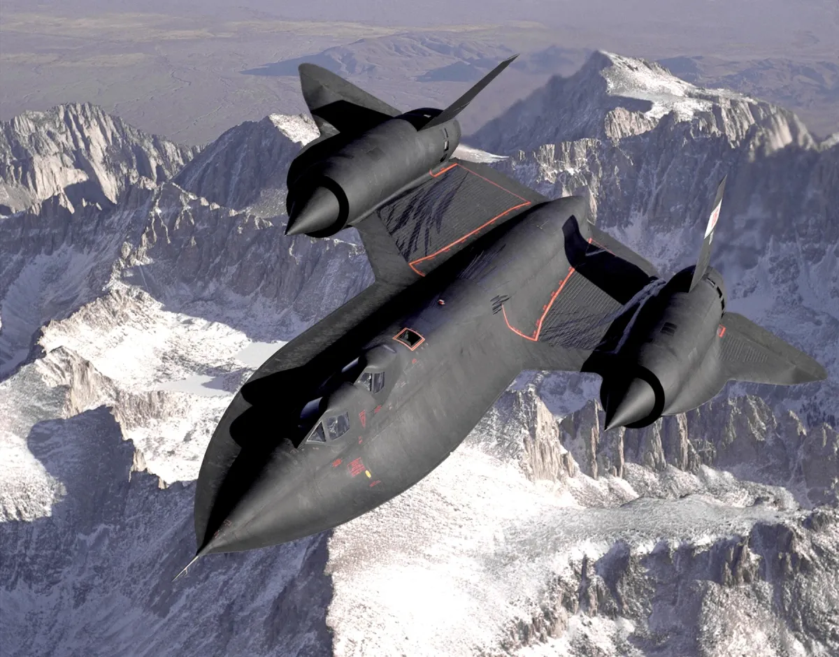
Editorial reasoning that is not itself a quotation is marked as such where it appears: the throat-is-best explanation of shock position, the model’s constants, and the description of a cone shock as weaker than a wedge shock. The photograph is a public-domain USAF image of a NASA-operated SR-71B, used as a reference photograph with its credit; it is not part of the model.
ABOUT THIS LAB
Educational. An original illustrative model built from public NASA documents, with every relationship cited and every constant labelled. Nothing here is the SR-71’s flight manual, its inlet schedule or a validated simulation, and nothing implies access to nonpublic material or any NASA endorsement of this site.
All aircraft